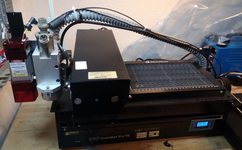
This article is about retro-fitting a diode laser engraving module to a LPKF ProMat 91s/VS PCB milling machine.
Background
I got this machine from a customer who were going to throw it (because it was old, it didn't work and nobody was using it anymore). Since the mechanics were still functional I decided to repair it as a side project and see what it could be used for. Eventually I decided to fit a laser engraving module to it, to be able to cut out simple solder paste stencils for prototype PCB projects.
Necessary parts and software
I am actually not sure where I got the software from. I think I found it on the Internet, or possibly it was on some disk that came with the machine.
The program "CircuitCam" I downloaded as a trial version but it is only used for PCB milling so I didn't actually need it. What I used:
- EAGLE pcb layout editor (I used 5.9.0) + the EAGLE CAM generator to generate the hpgl file.
- BoardMaster 3 to control the machine
- USB-Serial port converter (e.g Aten)
- Laser engraver module with "air assist" nozzle
- M5 to 1/8" "male-male" adapter for the hose to connect to the nozzle
- Mini compressor for a spray brush (e.g Biltema 17-370)
- PWM generator (e.g ZK-PP1K, ICstation, Amazon)
- Delay + PU/PD + level translation circuit (build yourself with veroboard, 74hct00, bc574, resistors, caps, LED, ...)
- 12V power supply for the laser module (e.g HPA-601250U3)
- Adapter plate to fix the laser module to the milling head (build yourself from Aluminum plate)
- Wood plates to use below the material you cut or engrave to avoid reflection to the laser
- Plastic plate to replace the aluminum worktop
- Plastic distances to increase the height of the mill/laser heads
- Honeycomb plate (base table for cutting) e.g Sculpfun Laser Honeycomb (sold at Amazon)
What you need to build
- The adapter plate to fix the laser module to the milling head
- Delay + PU/PD + level translation circuit
- Connector / adapter to the 9-pin end of the USB-Serial port adapter.
- Plastic plate to replace the aluminum worktop
- Plastic distances to increase the height of the mill/laser heads
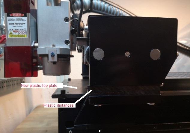
(Top plate and distances, cut out from the same material)
Repairs, and connecting to the USB adapter
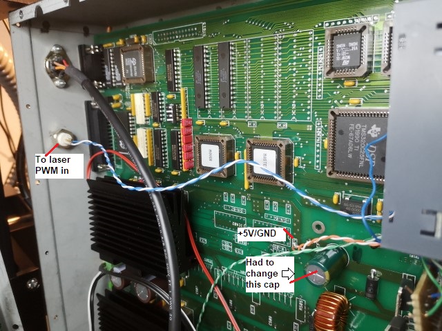
In my case I needed to replace some power supply capacitors inside the machine. Then a bit of soldering is needed to build an adapter from the 25-pin serial connector of the LPKF to the 9-pin serial port on the USB-Serial port adapter.
This is how I connected it.

Pinout from Plotter (PC side):
1 pg
3 out rx
2 In  tx
4 in rts
5 out cts
7 GND
8 dcd out
20 dtr in

This is the soldered adapter:
25-9-pin(f)
3-2 rx
2-3 tx
4-7 rts
5-8 cts
7-5 GND
8-1 dcd
20-4
You should turn off the FIFO in the advanced device settings of the USB-Serial converter device driver.
Start up:
- Power on the LPKF. Wait for it to find "home" position, be ready to switch off if it hits something.
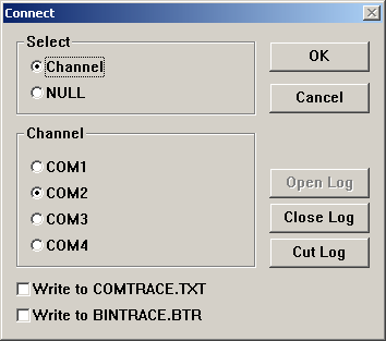
- Start Board Master. Connect (if not done before) trough the "Configuration-Connect" menu.
- Check the settings
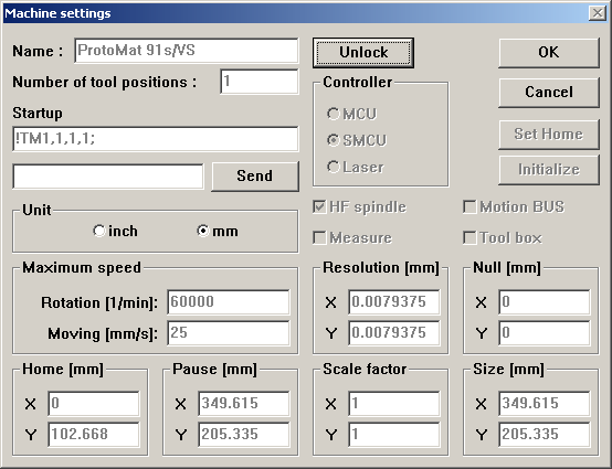
- Select "View" and "Machine"
- Select (in the toolbar) moving of head with mouse (the button with four small arrows). Then click somewhere on the work area. The machine should move there.
Note: Moving the head is for some reason essential. For some reason it won't work if you omit step 2 above.
Blocking the mill/drill head
When using the laser, we do not want the drill/mill head to interfere. I unplugged the motor and put a small M6 screw to prevent the head to be lowered by the magnetic coil / solenoid. I would have unplugged the coil as well but it had no connector.
I still have to wait 3 minutes when "starting the motor" in BoardMaster. It's very annoying but I don't know how to avoid it.
PWM gating and delay
Normally, when milling, the milling head need some time to travel down from the "PU" (Pen up) state to Pen Down state. When the PU/PD signal is used by the laser, the plotter stands still a few ms when the PD command arrives, before it starts moving. This causes the laser to burn a dot when engraving.
We need to delay the turn-on of the laser after the PD signal is received.
Parts:
- Blue Led
- Resistors: 49.9R, 330R, 22k, 47k, 100k trim potentiometer
- Capacitors: 10uF, 100nF
- IC: 74hct00
- Wires, BNC female connector, pin headers
You can not use 74LS00 because it has its own (approx 18k) internal pull-up on the input. Use CMOS equivalent (e.g 74HCT) instead.
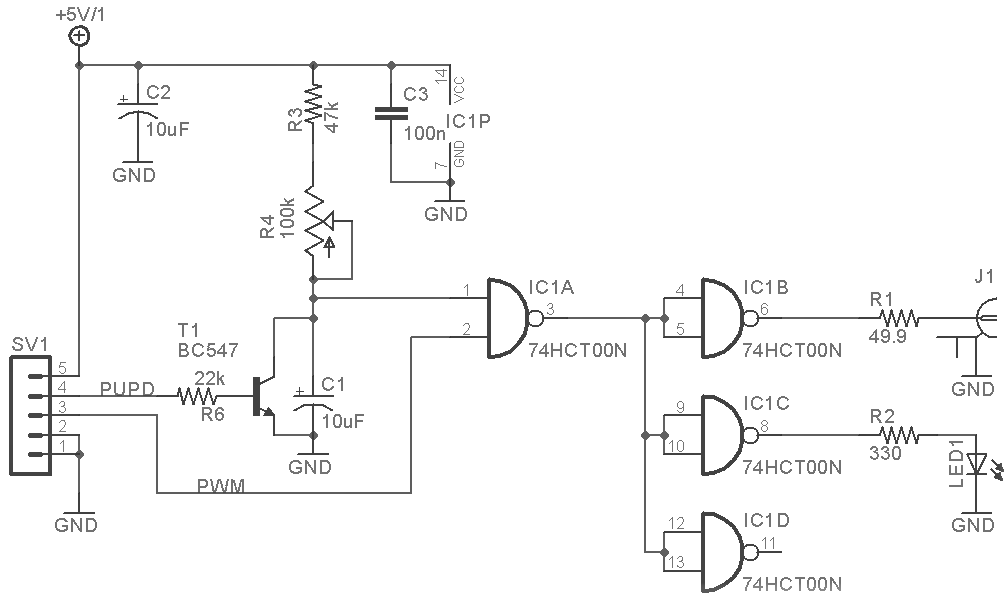
J1 is a bnc connector for a cable that goes to the laser PWM input.
I had a nasty ground loop forming from the laser module electronics (pwm input) and the frame of the heat sink, so I had to disconnect the heat sink from GND.
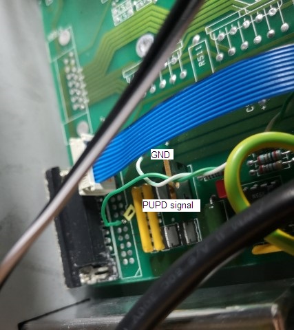
The PUPD signal, +5V, GND can be found in the LPKF (see images below). To open it you need to remove all of the small screws (they seem to have had a special price on screws) and the rubber feets.
ZK-PP1K has a screw connector for +5V (V+), GND (or V-) and PWM.
PWM settings
- For cutting trough a thin sheet (plastic) with the honeycomb plate and air assist, I use 1700Hz and 50% duty cycle.
- For engraving on wood I think I used 20% duty cycle.
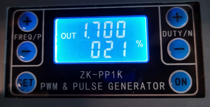
(PWM generator, e.g ZK-PP1K, ICstation, Amazon)
Preparing and loading a job from EAGLE
Preparing the HPGL file
- Start EAGLE and load the PCB
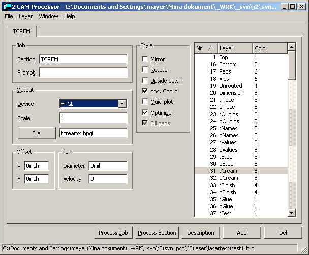
- Start the CAM Processor, Load your .pcb file, Select section: TCREAM, Device=HPGL, scale 1, All other parameters=0, Style: Pos coord, Optimize. Select layer 31.
- In the CAM generator, press "Proces job". The hpgl file will be created in the same directory.
- Move the hpgl file to C:\LPKF32\DATA
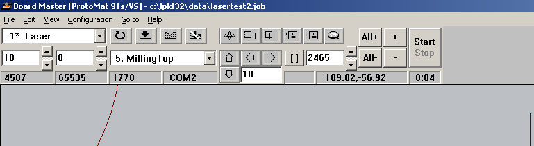
Importing hpgl to Board Master
- Select "File"-"Import"-"hpgl into"-"New LPR". Name the LPR something like "lasertest"
- Select your hpgl file (e.g "tcream.hpgl") in the file selection box. You will get a warning about tool assignments.
- Select "Edit"-"Tool Assignment...". Select "Phase 5 Milling Top" and the tool (one of the ones starting with "M"). I have defined my own tool "Laser".
- In the toolbar, use the drop-down menu to select "Current Phase" to "Phase 5 Milling Top". Your file should now show up on the work area.
Positioning the laser
- Right-click inside your loaded job. You can adjust the "Origin" parameters (X and Y) to move the job around on the work area.
- Select (in the toolbar) moving of head with mouse (the button with four small arrows). Then click in your job (at some lines) to see that the laser head moves to the right area/position. Redo the step above if you need to move it.
Starting the job
- You first need to have moved the head with the toolbar button with four small arrows. I don't know why, but it won't work otherwise.
- Start the motor by pressing the button with the crossed bended arrow. The motor will warm up for 3 minutes. We don't use the motor, but you need to turn it on anyway or the pen up/pen down functions will not work.
- Power on the laser and the compressor.
- Select the area you want to cut or engrave. Do this by clicking the button to the left of the magnifying glass, then use the mouse to select (your selection become white).
- Press the "+" button, your selection will be added (red).
- Press start button. The head will move to tool exchange position and ask you to insert the tool.
- Engraving/cutting starts. I get buffer overrun on some complex jobs sometimes, so I have to watch it all the time. I guess this has to do with the USB-Serial adapter, but I've found no solution yet. It seem to help to have task manager running in the background (or something that slows down the computer a bit).
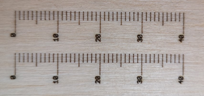
Engraving wood
There are A4 sized wood sheets available on Amazon for engraving. With "Air assist" I got the following result (bottom ruler is without "Air assist").
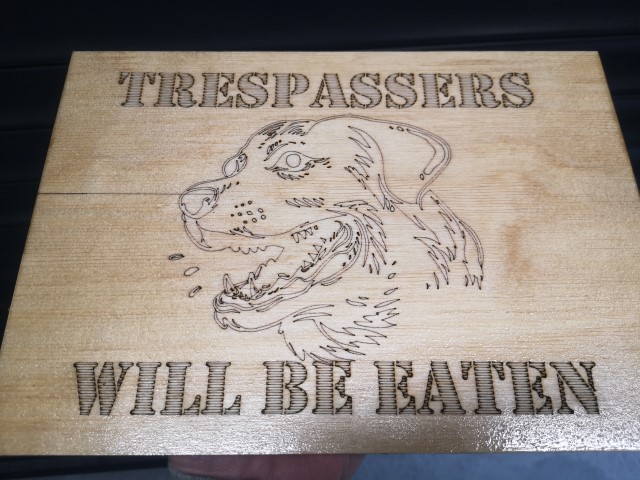
We can also engrave signs. The sign below was made in InkScape and exported as hpgl. To get the text fill/hatching an additional module "AxiDraw" is required.
Cutting a stencil
I use some kind of paper that is a mix between plastic and paper. It's semi-transparent.
When producing the hpgl file from EAGLE I have noticed that if the TCREAM layer contain rounded squares they get filled in the hpgl file. This takes time to cut out.
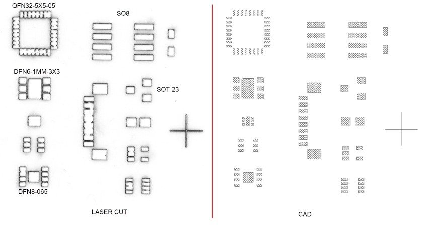
The problem is that the laser beam diameter cuts out too much, and the thin bars/strips left between the pads easily breaks.
EAGLE has a function to shrink the cream layer though. It's in the DRC form:
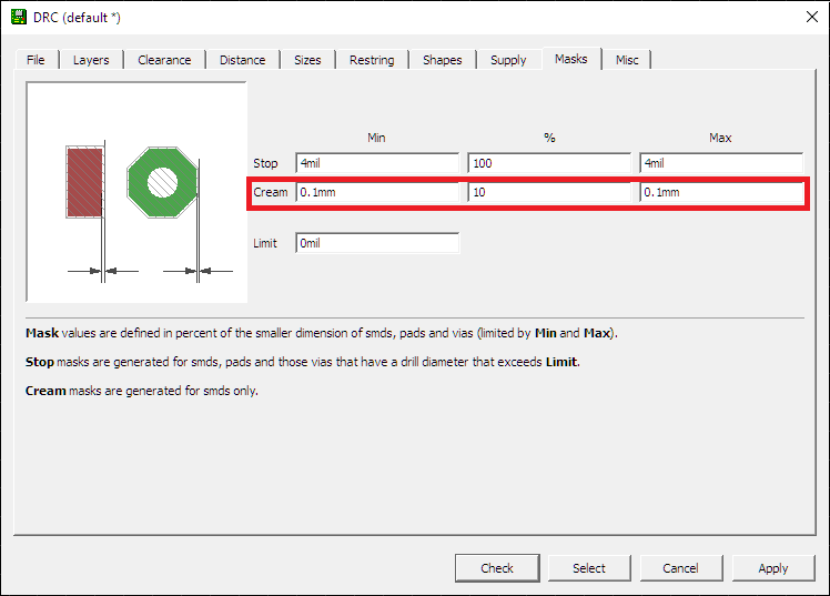
With the settings as above, we get the result below:
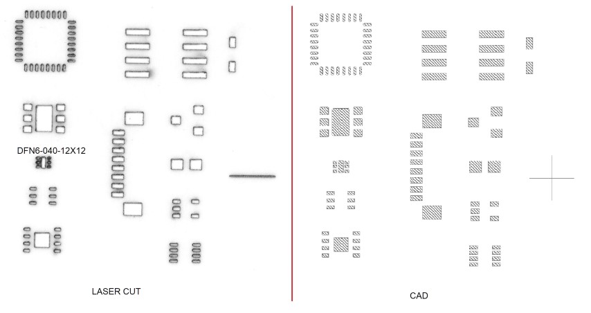
This result is actually usable, except for the DFN6-040-12x12 (pad pitch 400um, laser beam diameter is about 100um).